Star Micronics: Presents at MSV THE CNC SWISS-TYPE AUTOMATIC LATHE
September 18, 2024 / 1:45 PM
Expanded area for gate-shaped gang tool model, and a lineup of 4 types to suit your complex machining needs
![]()
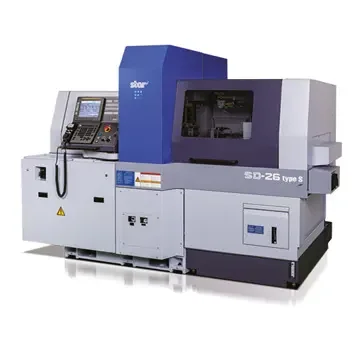
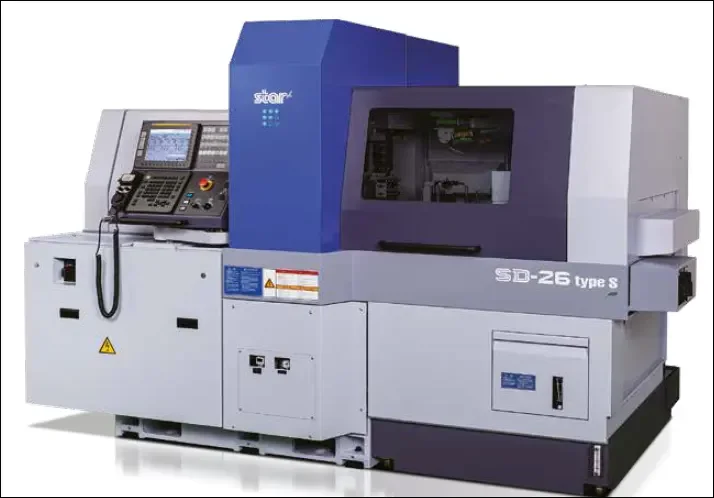
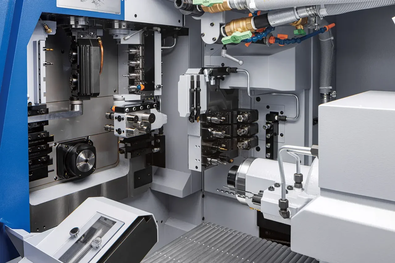
STAR SD-26
Star Micronics has developed the SD-26, a new model Swiss type automatic lathe (Note 1) capable of up to 26-dia. machining. It is mainly targeted at complex-shaped parts for automotive, hydraulic/pneumatic equipment and medical-related uses.
FEATURES OF THE SD-26
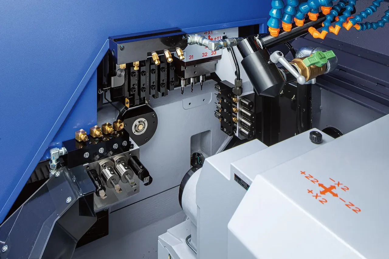
The SD-26 employs a gate-shaped tool post with a cross-guide structure (Note 2) that distributes the load evenly, arranged on the gang-type tool post for front-end machining so as to surround the guide bush that is the machining point for various tools such as turning tools and drills. The following 4 types are available, allowing you to select the most suitable tool post specification according to the application of the workpieces.
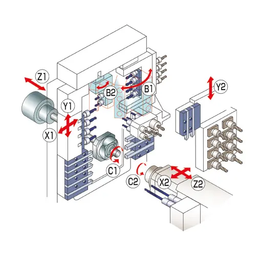
- Type S: Equipped with a 4-spindle facing-type milling unit with a tool swivel control axis (B-axis) capable of programmable simultaneous 5-axes-control. The upper section has one cartridge-type position with a 2nd B-axis mechanism that can provide swivel control for the dedicated tool unit. Various types of tool units can be mounted, including the world-first twin-thread whirling unit.
- Type G: Equipped with a 4-spindle facing-type milling unit with a tool swivel control axis (B-axis) capable of programmable simultaneous 5-axes-control. The upper section has two cartridge-type positions capable of mounting various tool units of existing models.
*The two cartridge-type positions are common to types G/E/C. - Type E: Equipped with a 4-spindle facing-type milling unit with a tool swivel control axis (B-axis) capable of programmable simultaneous 4-axes control.
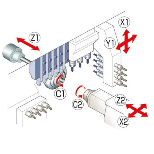
- Type C: Equipped with 4-spindle facing-type milling unit for which the angle is manually adjustable.
In addition, this type employs a guide bush/non-guide bush switching mechanism to flexibly support the increasingly diverse parts machining needs. This allows you to freely switch between the guide bush specification, which acts to prevent deflection of materials, enabling high accuracy machining of long and narrow parts such as motor shafts, and the non-guide bush specification (Note 3), which enables machining of short parts such as nuts without wastage, reducing the amount of waste material to be disposed of, on a single machine.
*Only Type S available for the European market
CONTROL FANUC FS-31I-B5 (TYPE S)
The 2-channel CNC control from Fanuc, the FS-31i-B5, controls the main side as well as the counter spindle for backworking, independently of each other. Programming is thus simplified, as each tool system (channel) is programmed separately. A total of 12 axes are controlled, 6 linear, 2 swivel axes and the two C axes.
Today, the Fanuc control is fully equipped as ex works and, with only one exception such as gear cutting, no additional options are required. In addition to the usual features such as position display, program editor, help function, geometry and wear off set, the control is equipped with the “STAR CUSTOM MENU”. This in-house development offers additional options that simplify setup, machine operation and workpiece machining. Each program created can be checked by the program check function and, in case of an error, gives a corresponding note so that it can be modified. A handwheel is integrated, with which the program can be rewound in real time. This makes it easier to retract the tools when space is limited in the machine. The workpiece counter is displayed in simplified form and also shows the cycle time achieved. A separate piece counter is stored for each tool position so that the life time of the cutting tools can be monitored.
KEY FEATURES OF THE SD-26S
High functionality
- You can select from 4 types for the optimum specification according to the shape of workpiece, from the "Type S", which is equipped with 4-spindle facing-type milling unit with B-axis control capable of simultaneous 5-axes control and cartridge-type tool unit with B-axis control mechanism, through to "Type C", equipped with a 4-spindle milling unit for which the angle is manually adjustable.
- For the cross-drilling unit on the front side, you can select from two types: the 4-spindle type dedicated for cross drilling, and the cartridge-type 4-spindle type on which tool units from existing models can be mounted. (Type S has the cartridge-type 4-spindle type only)
- A 8-spindle unit with Y-axis control is mounted for machining on the back side. The rotating tool unit can be mounted on all 8 positions, for expanded complex machining capability on the back side.
- An optional two turning tool holder can be mounted on the 8-spindle unit with Y-axis control. Enhanced turning capability on the back side realizes efficient division of machining on the front and back sides.
- With the hybrid function, with or without guide bush, the operator can decide for himself which technology is the better variant for the respective workpiece.
- The machine is equipped with our proprietary control method, the Star Motion Control system. (Types S and G) NC control is used to drastically reduce the required calculation time during operation and non-cutting time such as tool selection time, shortening the cycle time per part and achieving reduced energy consumption.
- The Y2 axis makes complex backworking possible.
High rigidity & accuracy
- The 4-spindle facing-type milling unit with B-axis control employs a structure for holding the upper and lower ends and maintains unit hold rigidity during swivel machining.
- The integrated spindle motors (built-in) for the main and sub spindles achieve higher dynamics and improved indexing accuracy.
- The machine employs various functions to maintain machining accuracy, such as flexible thermal displacement correction using temperature sensors arranged on each section of the machine body, and a dimension assist function that automatically corrects dimensional changes during temporary machine stoppages.
- The gate-shaped tool post for front side machining employs a cross-guide structure with an evenly distributed load. This reduces the moment load on the tool post guide rail during cutting, maintaining tool post rigidity.
- For very fine surfaces, rapid traverse can be reduced sequentially by means of M commands.
- The Star Motion Control System's spindle control utilizes the machining time of the previous stage to select the tool for the next stage and complete the approach, which suppresses vibration from excessive deceleration during spindle movement (only type S and G).
Note 1: "swiss type turning".
This "swiss type" machine technology was developed in Switzerland in the 1870s as a machining machine for watch components. It is also known as "Swiss-type turning" and has been designed for workpieces with extreme lengths compared to the outside diameter, as well as for small high-precision components. When long and narrow parts are machined with a universal lathe, the workpiece is bent. Thus, when finishing, the target dimension can no longer be maintained. Long turning technology uses a guide bush. The tool is always positioned at the same distance from the guide bush (<3mm). This means that the raw material is always guided, and the tool can machine the workpiece precisely and without bending. The diameter movement (X-axis) is made by the tool, the longitudinal movement (Z-axis) is made by the movable headstock.
Note 2: Uniform load cross guide structure
The gang-type tool post of the CNC automatic lathe is composed of X-axis and Y-axis slide tables. Each axis is usually supported by four linear guide bearings (eight linear guide bearings in total). The uniform load cross guide structure indicates a structure of the tool post equipped with 8 linear guide bearings evenly arranged around the guide bush as a cu ting point to generate a load. By distributing the cutting load to eight linear guide bearings, the load applied to each linear guide bearing is minimized and the tool post rigidity is improved. The employment of this tool post structure enables extended continuous operation with stable accuracy and prolongs the service life of the linear guide bearings.
Note 3: Version without guide bush "non guide bush".
The basis is the "Swiss-type" technology, but in this case the guide bush is dismantled, and the raw material is machined directly on the collet chuck and not on the guide bush. The machine can therefore machine a maximum workpiece length of 30mm. The golden rule for this is that the raw material diameter multiplied by 2.5 corresponds to the maximum workpiece length (L=Dx2.5). The great advantage of working without a guide bush is the more economical production of short workpieces, as well as the smaller rest piece, which is reduced by approx. 2/3 compared to guide bush machining.
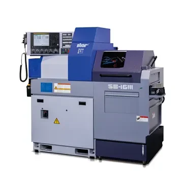
STAR SB-16III
Expansion of SB series lineup with a reputation for high rigidity and accuracy
Star Micronics has developed SB-16III, a new model of “SB Series” Swiss-Type Automatic Lathe (Note 1), capable of machining workpieces of maximum 16-mm diameter, aiming to serve machining of workpieces for the automotive, information communication, and other devices mainly in the Japanese and Asian markets. The product is scheduled to launch in April 2020.
Equipped with the highly rigid tool post which has our company’s unique slant-type slide guideway structure (Note 2), the SB Series enables continuous machining with stable accuracy. Since 2003, when SB-16, the initial model of the series was released, the series has been our company’s best seller, earning a strong reputation in the market.
To meet a wide range of needs in the market, the SB16III was designed to reduce the footprint of the machine with selected functionalities of the current models: SB-12R/16R/20R.
Additionally, this model adopts the latest version of NC system, installed with a variety of help features including the alarm help function which enables checking of alarm contents on NC screen. Furthermore,
the NC screen is mounted at an appropriate angle to the operator to ensure improved operability and workability.
FEATURES OF SB-16III
- It is equipped with the highly rigid tool post which has our company’s unique slant-type slide guideway structure which enables a long-time continuous machining with stable accuracy.
- The C-axis control function is installed as standard in the main and sub spindles.
- As an option, the product lineup newly includes the coolant-through type tool holder, which enables high-pressure supply of coolant through the inside of the tool from its tip without external pipes.
- A 10.4-inch color display is equipped with NC screen to improve visibility for operators.
- Various help functions which support operators’ daily work are installed to improve workability for setup and maintenance.
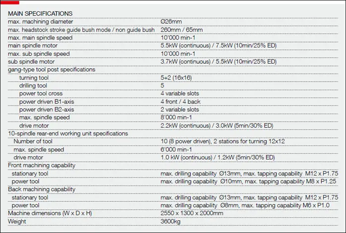
MAIN SPECIFICATIONS
(1) Max. machining diameter | ⌀ 16 mm | ||
(2) Max. headstock stroke | Stationary Guide Bush: | 205 mm | |
Rotary Guide Bush: | 155 mm | ||
(3) Max. main spindle speed | 10000 min-1 | ||
(4) Main spindle motor | 2.2 kW (continuous) / 3.7 kW (15 min/60 %ED) | ||
(5) Max. sub spindle speed | 9000 min-1 | ||
(6) Sub spindle motor | 0.55 kW (continuous) / 1.1 kW (15 min/50 %ED) | ||
(7) Gang-type tool post specifications | | ||
Tool(Selectable from the right) | 12 mm x 6 tools | ||
Sleeve holder | 4 tools | ||
Power tool(Selectable from the right) | 2-spindle cross drilling unit for ER11 | ||
Max. spindle speed | ER11: 7500 min-1 | ||
Drive motor | 0.5 kW | ||
(8) Back working tool post specifications | Stationary tool: 4 tools | ||
(9) Front machining capability | |||
Stationary tool | Max. drilling capability | ⌀ 10 mm | |
Max. tapping capability | M8 x P1.25 | ||
Power tool | Max. drilling capability | ER11: ⌀ 4 mm | |
ER16: ⌀ 6 mm | |||
Max. tapping capability | ER11: M3 x P0.5 | ||
ER16: M5 x P0.8 | |||
(10) Back machining capability | |||
Stationary tool | Max. drilling capability | ⌀ 8 mm | |
Max. tapping capability | M6 x P1.0 | ||
(11) Machine dimensions (W x D x H) | 1861 x 1060 x 1750 mm | ||
NOTE 1: Swiss-type automatic lathe
The Swiss-type automatic lathe was devised as watch component processing machinery in Switzerland in 1870s. Known as a “sliding head-type automatic lathe” as well, it has remarkable characteristics of high-precision cutting of components with longer length compared with the diameter.
In general, if long and narrow parts are processed with a general-purpose lathe, flexure will occur on the workpiece, making finishing with the correct dimensions impossible. The Swiss-type automatic lathe utilizes a guide bush to function as a material steady rest. The tool, positioned at a certain distance from the guide bush, gives a cutting motion only the direction of outside diameter. This allows the workpiece to be cut accurately with no flexure. As for axial motion, the headstock, rather than the tailstock, moves while clamping a workpiece.
NOTE 2: Slanted slide guideway structure
The machine main body base and the tool post are slanted, and each sliding surface is in a trapezoidal shape, called a dovetail structure. This structure allows each sliding surface to come into contact with its entire plane to improve the machine rigidity. The ball screw center and the cutting point are close to each other to reduce a load (moment load) applied in the direction of torsion caused by cutting resistance.
Company is exhibiting at the ALFLETH Engineering AG stand, hall P, stand no. 50
Photo Gallery